Introduction to Capacitors by IGee Emmanuel Eshiet
Here is a bit of the dry stuff, just to help understanding what a capacitor is and generally does. A capacitor is a small, most of the time, electrical/electronics component on most circuit boards, that can perform various functions. When a capacitor is placed in a circuit with an active current, electrons from the negative side build up on the closest plate(the negative flows to the positive, that is why the negative is the active lead, although many capacitors are not polarized). Once the plate can no longer hold them, they are forced past the dielectric and onto the other plate, thus displacing the electrons back into the circuit. This is called the discharge. Electrical components are very sensitive to voltage swings, and as such a power spike can kill those expensive parts. Capacitors condition DC voltage to other components and thus provide a steady power supply. AC current is rectified by diodes, so instead of AC, there are pulses of DC from zero volts to peak. When a capacitor from the power line is connected to ground and the DC will not pass, but as the pulse fills up the cap, it reduces the current flow and the effective voltage. While the feed voltage goes down to zero, the capacitor begins to leak out its contents, this will smooth the output voltage and current. Therefore a capacitor is placed inline to a component, allowing for absorbing of spikes and supplementing valleys, this, in turn, keeps a constant power supply to the component.
There is a multitude of different types of capacitors, they are often used differently in circuits. The all too familiar round tin can style capacitors are usually electrolytic capacitors. They are made with one or two sheets of metal, separated by a dielectric. The dielectric can be air (simplest capacitor) or other non-conductive materials. The metal plate foils, separated by the dielectric, are then rolled up similar to a fruit roll-up, and placed into the can. These work great for bulk filtering, but they are not very efficient at high frequencies.
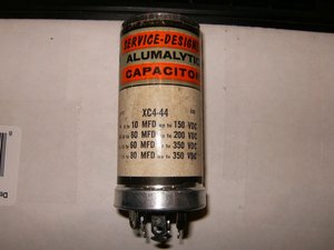
Here is a capacitor that some may still remember from the old radio days. It is a multi-section can capacitor. This particular one is a quad(4) section capacitor. All that means is, that there are four separate capacitors, with different values, contained in one can.
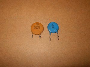
Ceramic disc capacitors are ideal for higher frequencies but are not good to do bulk filtering because ceramic disc capacitors get to big in size for higher values of capacitance. In circuits where it is vital to keep a voltage source stable, there is usually a large electrolytic capacitor in parallel with a ceramic disc capacitor. The electrolytic will do most of the work, whereas the small ceramic disc capacitor will filter off the high frequency that the big electrolytic capacitor misses.
Then there are tantalum capacitors. These are small, but have a greater capacitance in relation to their size than ceramic disk capacitors. These are more costly, but find plenty of use on the circuit boards of small electronic devices.

Although non-polar, old paper capacitors had black bands at one end. The black band indicated which end of the paper capacitor had some metal foil (which acted as a shield). The end with the metal foil was connected to the ground (or lowest voltage). The main purpose of the foil shield was to make the paper capacitor last longer.

Here is the one that we are most likely interested in the most, when it comes to iDevices. These are very small in comparison to the before listed capacitors. They are the Surface Mount Device (SMD) caps. Even so they are miniature in size compared to the previous capacitors, the function is still the same. One of the importance, besides the values of these capacitors, is their "package". There is a standardization for the size of these components, i.e. package 0201 - 0.6 mm x 0.3 mm (0.02" x 0.01"). The package size for the ceramic SMD capacitors follows the same package for SMD resistors. This makes it almost impossible to determine if it is a capacitor or a resistor by visualization. Here is a good description of the individual size based on package numbers.

SMDs on a PCB

Large SMDs
Testing Capacitors
Determining the value a capacitor has can be accomplished in a few ways. Number one, of course, is a marking on the capacitor itself.
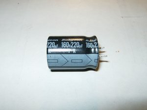
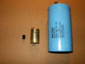
This particular capacitor has a capacitance of 220μF (micro farad) with a tolerance of 20%. This means that is could be anywhere between 176μF and 264μF. It has a voltage rating of 160V. The arrangement of the leads all show that it is a radial capacitor. Both leads exit on one side versus an axial arrangement where one lead exits from either side of the capacitors body. Also, the arrowed stripe on the side of the capacitor indicates the polarity, the arrows are pointing towards the negative pin.
Now the main question here is, how to check a capacitor to see if it needs replacing.
To perform a check on a capacitor while it is still installed in a circuit, an ESR meter will be necessary. If the capacitor is removed from the circuit then a multimeter set as an ohm meter can be used, but only to perform an all-or-nothing test. This test will only show if the capacitor is completely dead, or not. It will not determine if the capacitor is in good or poor condition. To determine if a capacitor is functioning at the right value (capacitance), a capacitor tester will be necessary. Of course, this also holds true to determine the value of an unknown capacitor.
The meter used for this Wiki is the cheapest one available at any department store. For these test it is also advisable to use an analog multimeter. It will show the movement in a more visual way than a digital multimeter that only display rapidly changing numbers. This should enable anybody to perform these tests without spending a fortune on something like a Fluke meter.
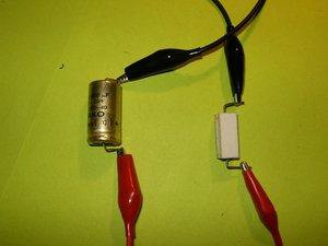
Always discharge a capacitor before testing it, it will be a shocking surprise if this does not get done. Very small capacitors can be discharged by bridging both leads with a screw driver. A better way of doing it would be by discharging the capacitor through a load. In this case alligator cables and a resistor will accomplish this. Here is a great site showing how to construct a discharge tools.
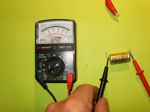
To test the capacitor with a multimeter, set the meter to read in the high ohms range, somewhere above 10k and 1m ohms. Touch the meter leads to the corresponding leads on the capacitor, red to positive and black to negative. The meter should start at zero and then moving slowly toward infinity. This means that the capacitor is in working condition. If the meter stays at zero, the capacitor is not charging through the battery of the meter, meaning it is not working.
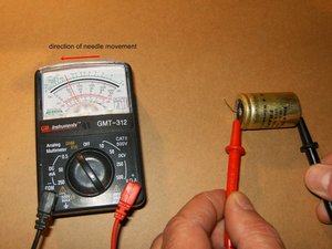
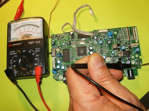
This will also work with SMD caps. Same test with the needle of the multimeter moving slowly in the same direction.
One more test that one can do on a capacitor is a voltage test. We know that capacitors store a potential difference of charges across their plate, those are voltages. A capacitor has an anode which has a positive voltage and a cathode which has a negative voltage. One way to check if a capacitor is working is to charge it up with a voltage and then read the voltage across the anode and cathode. For this it is necessary to charge the capacitor with voltage, and to apply a DC voltage to the capacitor leads. In this case polarity is very important. If this capacitor has a positive and negative lead, it is a polarized capacitors (electrolytic capacitors). Positive voltage will go to the anode, and negative goes to the cathode of the capacitor. Remember to check the markings on the capacitor to be tested. Then apply a voltage, which should be less than the voltage the capacitor is rated for, for a few seconds. In this example the 160V capacitor will be charged with a 9V DC battery for a few seconds.

After the charge is finished, disconnect the battery from the capacitor. Use the multimeter and read the voltage on the capacitor leads. The voltage should read near 9 volts. The voltage will discharge rapidly to 0V because the capacitor is discharging through the multimeter. If the capacitor will not retain that voltage, it is defective and should be replaced.
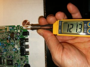
The easiest of course will be to check a capacitor with a capacitance meter. Here is a FRAKO axial GPF 1000μF 40V with a 5% tolerance. Checking this capacitor with a capacitance meter is straight forward. On these capacitors, the positive lead is marked. Attach the positive (red) lead from the meter to that and the negative (black) to the opposite. This capacitor shows 1038μF, clearly within its tolerance.

To test an SMD capacitor may be difficult to do with the bulky probes. One can either solder needles to the end of those probes, or invest in some smart tweezers. The preferred way would be using smart tweezers.
Some capacitors do not require any test to determine failure. If a visual inspection of the capacitors reveal any sign of bulging tops, those need to be replaced. This is the most common failure in power supplies. When replacing a capacitor, it is of utmost importance to replace it with a capacitor of the same, or higher value. Never subsidize with a capacitor of lesser value.

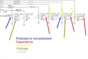
If the capacitor that is going to be replaced or checked, does not have any markings on it, a schematic will be necessary. The image below from here shows a few symbols for capacitors that are used on a schematic.

This excerpt from an iPhone schematic indicates the symbol for capacitors as well as the values for those capacitors.